 There is an old saying that goes something
like this "A man who has a clock always knows what time it
is. A man who has more than one clock is never sure what time
it is." This page is devoted to my attempt to solve that
problem through the use of a Jeff Thomas and John Miktuk designed
GPS controlled Nixie clock.
There is an old saying that goes something
like this "A man who has a clock always knows what time it
is. A man who has more than one clock is never sure what time
it is." This page is devoted to my attempt to solve that
problem through the use of a Jeff Thomas and John Miktuk designed
GPS controlled Nixie clock.
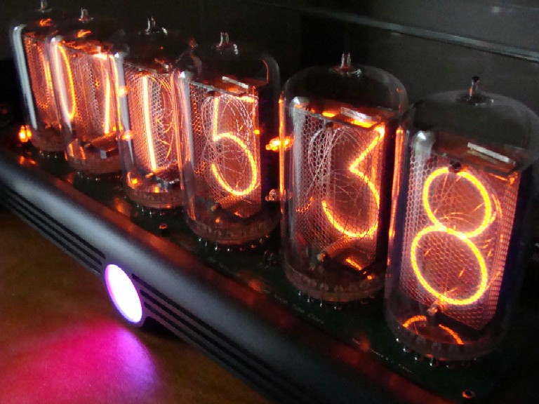
Now, if you don't know what Nixies
are (originally from Numeric Indicator Experimental-1) they are
a product of the mid 50's to early 70's. They predate the light
emitting diode. They look like a vacuum tube but are in fact a
form of neon light. Nixies consist of a sealed glass tube (like
a vacuum tube) with a single internal cathode plate at the rear
and, in front of that, 10 successive formed wire digits. Each
anode digit and the common cathode has a pin at the bottom of
the neon filled tube. To light a digit you simply apply approximately
170VDC between the common cathode and the appropriate digit pin.
The energized digit causes a warm glow of neon to light up around
it. Nixies however, unlike vacuum tubes, have no heater and operate
cold.
I'm sure most people are familiar with
the Global Positioning Satellite (GPS) system and that with them
you are able to determine your position and speed (even walking)
very accurately. What makes it all possible is that each satellite
in the system has four atomic clocks on board, and those clocks
are compared with those in Building 78 at the Naval Observatory
twice a day to make sure they're accurate to the billionth of
a second (if GPS used time scales less accurate, say to a thousandth
of a second, its margin of error would equal roughly the distance
between Ottawa and Montreal). This Nixie clock makes use of
that extremely accurate GPS satellite time output so that in essence
I have a cesium time reference in my house.

 I was originally "turned on" to Nixie
clocks by an article in an IEEE Spectrum magazine passed to me. In the
article there was a GPS version designed by Katsushi Matsubayashi
of Tokyo that inspired me to think about designing my own. The
first thing I did however was secure 6 beautifully large NOS (New
Old-Stock) ZM5680M Nixie tubes. My thinking here was the supply
of Nixies is fixed and limited so I should get them first. If
I sat on the idea for a while I'd at least have the tubes while
any design I came up with to run them, even if delayed for years,
could evolve with the times and technology. My hope was to use
them to create a clock driven by a GPS receiver unit so that it
was, in fact, an in-house cesium time standard. Using momentary
switches I would be able to selectively display sidereal time,
equation of time, sunrise time, sunset time, latitude, longitude
& elevation. I would also be able to set alarm time on it
through rotary switches and have that alarm output drive a high
fidelity sound board. Different alarm sounds were also to be selectable
by a rotary switch. Additionally the clock would command the sound
board to generate selectable clock sounds for seconds, the quarters
and on the hour. Possibly the sound card could be amplified by
car audio components. I did a fair amount of research into the
algorithms needed to convert exact time to the outputs above.
The following was my basic idea...
I was originally "turned on" to Nixie
clocks by an article in an IEEE Spectrum magazine passed to me. In the
article there was a GPS version designed by Katsushi Matsubayashi
of Tokyo that inspired me to think about designing my own. The
first thing I did however was secure 6 beautifully large NOS (New
Old-Stock) ZM5680M Nixie tubes. My thinking here was the supply
of Nixies is fixed and limited so I should get them first. If
I sat on the idea for a while I'd at least have the tubes while
any design I came up with to run them, even if delayed for years,
could evolve with the times and technology. My hope was to use
them to create a clock driven by a GPS receiver unit so that it
was, in fact, an in-house cesium time standard. Using momentary
switches I would be able to selectively display sidereal time,
equation of time, sunrise time, sunset time, latitude, longitude
& elevation. I would also be able to set alarm time on it
through rotary switches and have that alarm output drive a high
fidelity sound board. Different alarm sounds were also to be selectable
by a rotary switch. Additionally the clock would command the sound
board to generate selectable clock sounds for seconds, the quarters
and on the hour. Possibly the sound card could be amplified by
car audio components. I did a fair amount of research into the
algorithms needed to convert exact time to the outputs above.
The following was my basic idea...
 The more I got into it the more it
seemed the hardware would be trivial and that the real challenges
were in the machine code software that would allow the PIC microcontroller
to convert the serial GPS output from the GPS receiver into the
display outputs listed above. As I stated on my Propeller Clock page my abilities in machine
code programming are very limited! It was about this time that
I joined an online Nixie clock group only to have Jeff Thomas
(above) announce, within a week of my joining, he was coming out
with a GPS
clock kit that, whoa and behold, used the very same tubes
I had already bought. After some deep thought and a few inquiries
I decided that there was no point in re-inventing the wheel and
that his kit could possibly be the purchased heart of my original
idea and so joined the waiting list for the kit. In a few months
Jeff emailed me that the kits were ready and I took the plunge
and ordered one.
The more I got into it the more it
seemed the hardware would be trivial and that the real challenges
were in the machine code software that would allow the PIC microcontroller
to convert the serial GPS output from the GPS receiver into the
display outputs listed above. As I stated on my Propeller Clock page my abilities in machine
code programming are very limited! It was about this time that
I joined an online Nixie clock group only to have Jeff Thomas
(above) announce, within a week of my joining, he was coming out
with a GPS
clock kit that, whoa and behold, used the very same tubes
I had already bought. After some deep thought and a few inquiries
I decided that there was no point in re-inventing the wheel and
that his kit could possibly be the purchased heart of my original
idea and so joined the waiting list for the kit. In a few months
Jeff emailed me that the kits were ready and I took the plunge
and ordered one.

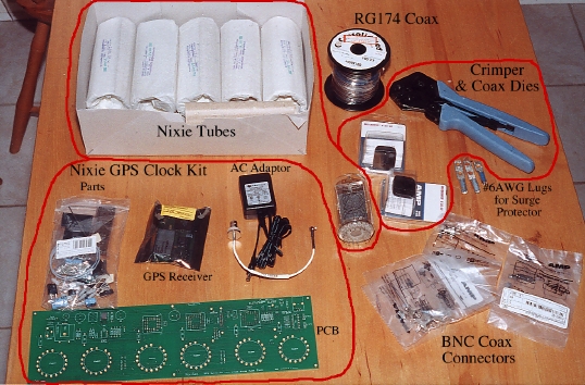
 Above you can see the kit and other
peripheral items not included such as the tubes etc. The building
of the kit was very straight forward as it was all well documented.
It went together quite quickly and without any issues at all.
Above you can see the kit and other
peripheral items not included such as the tubes etc. The building
of the kit was very straight forward as it was all well documented.
It went together quite quickly and without any issues at all.
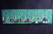
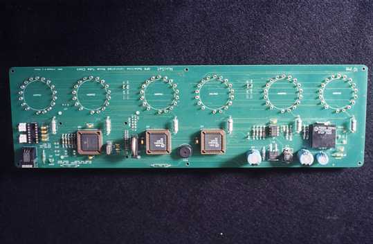
 The pictures above show the board near
completion. The colon indicators have yet to be done on the primary
side of the board. The GPS unit can be seen on the secondary side
of the board. There are a few mods yet to be done which get described
below.
The pictures above show the board near
completion. The colon indicators have yet to be done on the primary
side of the board. The GPS unit can be seen on the secondary side
of the board. There are a few mods yet to be done which get described
below.
 The next item I had to resolve was
the base. Jeff offers a good one for a very reasonable price but
I wanted something a little different. I wanted to capture a tinge
of "retro" feel. A lot of different (even wacky) ideas
were explored. Some of the more esoteric ideas were definitely
going to be prohibitive in cost and time as they involved casting
complex shapes. After many sketches I came up with a basic idea
which I simplified a bit to allow for ready machining. The idea
was a black anodized aluminum block with soft corners (like some
50's appliances), a bit of heatsink-look and a back-lit logo.
I designed the base
on Pro/E.
The next item I had to resolve was
the base. Jeff offers a good one for a very reasonable price but
I wanted something a little different. I wanted to capture a tinge
of "retro" feel. A lot of different (even wacky) ideas
were explored. Some of the more esoteric ideas were definitely
going to be prohibitive in cost and time as they involved casting
complex shapes. After many sketches I came up with a basic idea
which I simplified a bit to allow for ready machining. The idea
was a black anodized aluminum block with soft corners (like some
50's appliances), a bit of heatsink-look and a back-lit logo.
I designed the base
on Pro/E.

The base also had to accommodate the glass cover. I
went locally to Northern Art Glass and inquired about starphire crystal.
starphire crystal is essentially extremely clear glass. Even the
edges are clear (not green - see below).
 While they could special order the
cut & polished glass and put it all together they could not
guarantee holding to machined (3 decimal) dimensions. They could
work to +/- 1/32". This meant I had to get the glass done
first so I could measure its actual dimensions before finalizing
the machined base design. The starphire crystal was always referred
to as 6mm but I was told it was actually 1/4". I designed
a cover on Pro/E accordingly allowing me to give them the piece
dimensions for front, end and top. They did a wonderful job on
the cover but there is a slight overhang (0.023" front and
back) on the top piece. It turns out that starphire crystal is
not 1/4" or even 6mm but rather 0.227" thick. While
this could have been avoided had I known the actual crystal thickness
the very slight overhang is not readily noticed and does provide a
sure hand grip when lifting the glass.
With the glass received and measured
the base dimensions were finalized and prepared for machining.
This is a case where I didn't feel my mill/drill was up to the job. The raw material
alone was going to be over 30lbs and the rounded corners meant
machining a curve (CNC) something my etch-a-sketch mill/drill
couldn't do. I had previously submitted my paper drawing to several
machine shops and went for the best quote. That turned out to
be Alzar Industries
on 77 Auriga Drive Nepean Ontario. Transfer of the design was
easy. From my computer I simply dropped the Pro/E model into their
FTP dropbox and they were off and running. It would take 8 business
days to complete. While this was going on I turned my attention
to the logo/LED board PCB.
The actual logo design itself came
to me fairly quickly however the rest involved a bit of thought
as it was to have 3 back-lit sections, blue, red and blue. The
logo was etched out of 0.010 stainless shim stock. I had
fotofab quote the etching but it was going to be over $1000 even with me supplying the phototools. As a result this part is currently not finished. This is why there is a bright glow in
the lower center of the clock photos.
While they could special order the
cut & polished glass and put it all together they could not
guarantee holding to machined (3 decimal) dimensions. They could
work to +/- 1/32". This meant I had to get the glass done
first so I could measure its actual dimensions before finalizing
the machined base design. The starphire crystal was always referred
to as 6mm but I was told it was actually 1/4". I designed
a cover on Pro/E accordingly allowing me to give them the piece
dimensions for front, end and top. They did a wonderful job on
the cover but there is a slight overhang (0.023" front and
back) on the top piece. It turns out that starphire crystal is
not 1/4" or even 6mm but rather 0.227" thick. While
this could have been avoided had I known the actual crystal thickness
the very slight overhang is not readily noticed and does provide a
sure hand grip when lifting the glass.
With the glass received and measured
the base dimensions were finalized and prepared for machining.
This is a case where I didn't feel my mill/drill was up to the job. The raw material
alone was going to be over 30lbs and the rounded corners meant
machining a curve (CNC) something my etch-a-sketch mill/drill
couldn't do. I had previously submitted my paper drawing to several
machine shops and went for the best quote. That turned out to
be Alzar Industries
on 77 Auriga Drive Nepean Ontario. Transfer of the design was
easy. From my computer I simply dropped the Pro/E model into their
FTP dropbox and they were off and running. It would take 8 business
days to complete. While this was going on I turned my attention
to the logo/LED board PCB.
The actual logo design itself came
to me fairly quickly however the rest involved a bit of thought
as it was to have 3 back-lit sections, blue, red and blue. The
logo was etched out of 0.010 stainless shim stock. I had
fotofab quote the etching but it was going to be over $1000 even with me supplying the phototools. As a result this part is currently not finished. This is why there is a bright glow in
the lower center of the clock photos.

The logo sits
against the inside of the front glass with both held in place
by a 1.375 aluminum tube. The length of the tube was designed
to allow the 30° light from the LEDs to properly spread. The
tube is held in place by the front center mounting screw used
to secure the clock PCB to the base. Inside the tube are 0.003"
stainless steel shim stock "section separators" that
keep the different colour lights within their own sections. By threading screws
from the inside of the tube outward the 0.003" stainless steel shim stock
"section separators" could be held in place by using the sloted heads. At
the far end is the LED board
providing the illumination. I designed and laid out this PCB for
mounting the LEDs, connector and a brightness adjusting potentiometer.
Power for the LED board is tapped from the +12V supply although
a larger switched mode power supply (wall adapter) was required
as the one supplied for the kit was near it's limit (850mA). The
LED board is keyed to the tube so that it can't rotate out of
alignment and is held in place by spring clips.
When the layout was complete the LED
board PCB was sent out by ftp to APCircuits of Calgary Alberta for their "P1" service. These guys offer
an amazing service for small quantity PCBs. Within minutes of
dropping the files off and emailing them they contacted me and
acknowledged receipt and that all files were OK. Periodically
after that you get automated emails telling you where your boards
are in the production run. If you get the files in before 11:00am
the boards are shipped (Fedex rush) the afternoon of the following
day and I had them in hand the morning after that. Amazing!

 The first thing one should think about
when putting up an antenna is lightning. Why? You are in essence,
without any other precautions, building a lightning rod with the
antenna mount acting as the rod while the coax cable is acting
as the grounding conductor. A coax cable does not
make for a good lightning ground conductor and dangerous and damaging
potentials could develop. Take a look at the picture above of
a typical storm passing over a town. I wasn't about to throw the
dice and say that one day one of those 20,000A bolts of electricity
wouldn't hit my so-so lightning rod! At the base of each of those
hits above are people who had to live with the consequences of
their individual decisions (good or bad). If you want to get an
inkling of how likely are you to get hit check out this map. I can summarize the 3 pronged rational of the National Electrical
Code (NEC) as follows.
The first thing one should think about
when putting up an antenna is lightning. Why? You are in essence,
without any other precautions, building a lightning rod with the
antenna mount acting as the rod while the coax cable is acting
as the grounding conductor. A coax cable does not
make for a good lightning ground conductor and dangerous and damaging
potentials could develop. Take a look at the picture above of
a typical storm passing over a town. I wasn't about to throw the
dice and say that one day one of those 20,000A bolts of electricity
wouldn't hit my so-so lightning rod! At the base of each of those
hits above are people who had to live with the consequences of
their individual decisions (good or bad). If you want to get an
inkling of how likely are you to get hit check out this map. I can summarize the 3 pronged rational of the National Electrical
Code (NEC) as follows.
- 1) Ground the antenna structure with a large
copper conductor (#6AWG) to carry the bulk of the
- current safely to ground. This will also
tend to clamp the resultant antenna voltage as close to
- ground as possible (lightning is a constant
current source!). If you have an external ground
- reference then ground it to that.
-
- 2) Ground the shield of the coax to your
main house ground at the same point your main hydro
- panel is grounded to (important) so that
any energy coming down the cable shield is safely
- discharged to ground and that there is no
current-inducing difference between the coax shield
- ground and the hydro ground. That only leaves
the center conductor of the coax.
-
- 3) For this you use a good quality in-line
surge protector. I chose a Citel unit, P8AX-09-BW/FF,
- because it was panel mount, BNC to BNC and
50 ohm (same as the GPS antenna/coax). These will
- do double duty and also solve the former
problem of grounding the shield. These units contain gas
- tubes between the center conductor and ground
(the shield). Normally they do nothing (high
- impedance) but when the voltage gets excessive
they flash-over and conduct essentially clamping
- the center conductor close to ground too.
By doing all these things you give
an easy path for the majority of the hit to get to ground, you
keep the voltage developed at the antenna low and if the ground
potential does resultantly rise then all things are referenced
together and they will tend to "ride the wave" together
(a good thing). That's why it's important to ground the coax at
the hydro ground point! Remember that the GPS is ultimately powered
by hydro and if the coax & hydro ground points are different
they may try to equalize with large currents (a bad thing). Apart
from all the above having the antenna sitting on a good ground
plane enhances performance too. The funny thing is having followed
all of this I now notice all the satellite dish installations
(done by cable providers) which are not done to code.
The next thing I had to consider was
how to protect the antenna from the elements. The antenna as received
has the coax entering its housing through a hole which did not
appear to be sealed (it may in fact be sealed inside but I couldn't
see it). Since I wanted high availability this meant the antenna
had to have a good view of the sky which meant it couldn't be
placed on a window sill but had to be placed outdoors and hence
protected. This is where one must become a "McGuiver".
I came up with the basic design fairly quickly but had a fair
amount of difficulty finding an appropriate workable environmental
cover. The first three iterations were rejected
designs. I finally bumped into the solution at Home Depot
while waiting for my 3rd cover to arrive. It is a lightweight
white lamp glass which I could use inverted. The opening on the
lamp glass was large enough to allow the antenna to fit through
while the domed shape would allow snow and rain to be shed. Putting
all the above requirements together led me to the following
Antenna
Installation Design. With this done the only thing left was
to get on with the job and build it.
The design I came up with was based
on materials I had in the garage so it was merely a matter of
firing up my MIG, lathe & bandsaw and putting it all together.
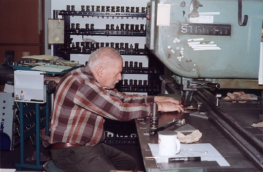
The only item that I could not do was
a special "D-punch" for the surge protector bracket.
The surge protector I used was panel mount and needed a "D"
hole so it wouldn't rotate when tightened to the panel. Here Forel
Metal Products was able to help me out (photo below) as they
had the 0.501" x 0.469" D-punch.
 The rest of the bracket was pretty
straight forward.
The rest of the bracket was pretty
straight forward.

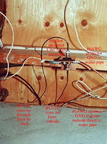
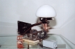 The pictures above show the result
before mounting. In the left picture you can see all the parts
relative to one another. The rear of the surge protector bracket
with the black lug brace can be seen in the lower left. The right
picture shows it with the environmental cover on. The #6AWG grounding
connection can also be seen. In the lower left of the right picture
the front of the surge protector & bracket can be seen. Since
the 19ft antenna coax was not long enough to get all the way inside
the house a weather tight exterior junction box (lower right)
is used to protect the BNC connection to the extender cable. An
AMP crimper (see the clock kit photo above) with RG174 hex crimp
dies were used to make the BNC connections while a Paladin CST
coax stripper was used to prepare the cable. All crimps when completed
were protected with heatshrink while the connection inside the
exterior junction box, after mating, was further covered with
1" heat-shrink and the ends were ty-wrapped tight to the cable.
The #6AWG connections for the surge protector were simply made
with a T&B lug crimper.
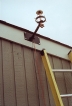
The following photos show the antenna
installation (left), the cable run into the house and grounding
(right).
The pictures above show the result
before mounting. In the left picture you can see all the parts
relative to one another. The rear of the surge protector bracket
with the black lug brace can be seen in the lower left. The right
picture shows it with the environmental cover on. The #6AWG grounding
connection can also be seen. In the lower left of the right picture
the front of the surge protector & bracket can be seen. Since
the 19ft antenna coax was not long enough to get all the way inside
the house a weather tight exterior junction box (lower right)
is used to protect the BNC connection to the extender cable. An
AMP crimper (see the clock kit photo above) with RG174 hex crimp
dies were used to make the BNC connections while a Paladin CST
coax stripper was used to prepare the cable. All crimps when completed
were protected with heatshrink while the connection inside the
exterior junction box, after mating, was further covered with
1" heat-shrink and the ends were ty-wrapped tight to the cable.
The #6AWG connections for the surge protector were simply made
with a T&B lug crimper.
The following photos show the antenna
installation (left), the cable run into the house and grounding
(right).


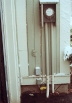
 Having installed it on a warm sunny
day it snowed that very night (lower left) and rained all the
following day. Below right shows the snow covered grey coax junction
box above the green phone entrance box. The cables can be seen
entering the house right next to the phone box.
Having installed it on a warm sunny
day it snowed that very night (lower left) and rained all the
following day. Below right shows the snow covered grey coax junction
box above the green phone entrance box. The cables can be seen
entering the house right next to the phone box.

 Taking advantage of this test opportunity
I fired up the clock PCB and within 15min it had completed a cold
acquisition of the overhead GPS satellites. Everything worked
and in the months since, no issues.
Taking advantage of this test opportunity
I fired up the clock PCB and within 15min it had completed a cold
acquisition of the overhead GPS satellites. Everything worked
and in the months since, no issues.

Final assembly
presented no issues at all and the clock has worked flawlessly since I've
finished it. I did make one modification to the board and that was to put a 1MΩ
resistor to pull up the enable pin (4) on the MAX 771 power supply chip (that
generates the high voltage for the Nixies) then cut the track to the PIC micro
which normally holds it to GND and put a switch in series with that cut track.
The switch is mounted on the back of the base. This allows me to keep the clock
running at all times but be able to switch off the Nixies so as to prolong their
life. Even thought the Nixies are off there is a tiny on board green LED which
indicates all is well with it's 1 pulse per second heartbeat. Whenever I need a
time reading or want to put it on display I switch on the Nixies but otherwise I
generally leave them off. Given that there is a lovely soft hi-lo beep on the
hour this works fine.


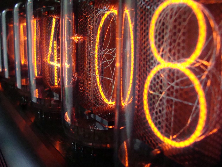
When they are on they are such a fascinating delight to
watch. The combination of metal and glass is exquisite. It's delightful to watch
the thick orange glow magically appear on the fine wire
digit then instantly disappear as a different wire takes its turn. The
oscillating change in depth as each digit lights up in turn is captivating.
Within each tube each lighted wire lights up its neighboring wires and the glass just like neon bar
sign would light up the night. Yet for all the nostalgia there is also a certain
thrill to hear the NRC
time signal countdown broadcast on CBC radio near 1:00pm. Sure enough at the exact sound of the last
long beep the clock rolls over from 12:59:59 to 1:00:00. Now, despite the old
saying, this man who has more than one clock is always sure
what time it is.

Back to 
Back